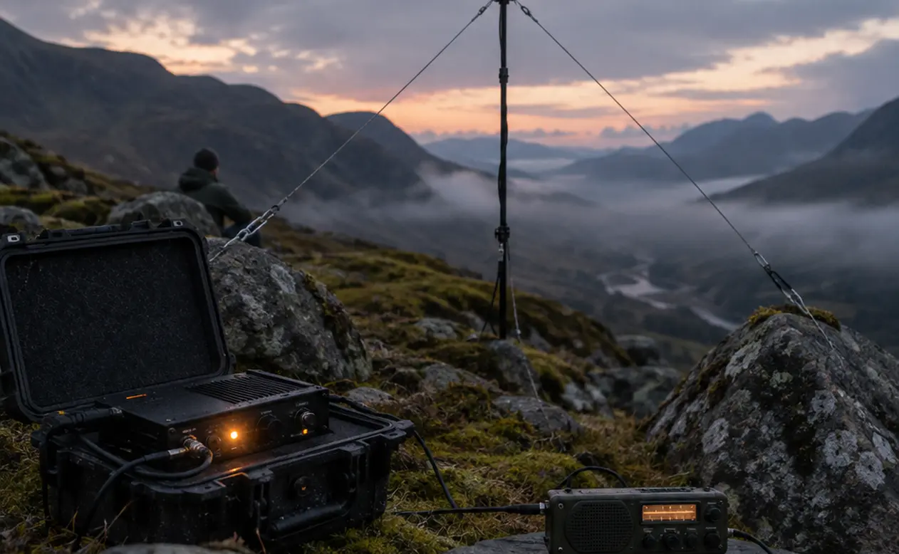
When a Slate Gorge Swallows the Listening Post
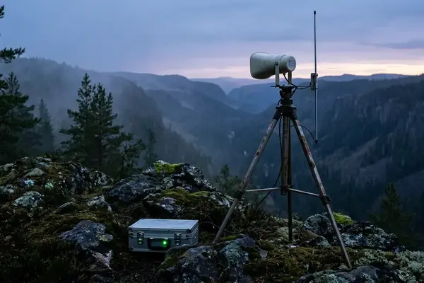
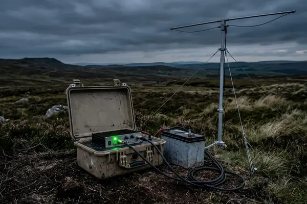
Imagine dusk in a steep slate gorge. A battery-powered FM transmitter sits above two weatherproofed receivers, all positioned by eye. Cooling air begins draining down the slope. Wind buffets the documentation microphones and buries the receivers’ small loudspeakers. Across the gorge, a delayed return from the opposite wall tangles with a delicate modular drone.
Why does unheard electronic music, composed under controlled studio conditions, become so difficult to follow here?
The first task is to locate the breakdown. A clean headphone feed beside a wind-buried listening radio places the problem after demodulation: audible valley echoes affect the loudspeaker-to-listener path rather than the FM carrier, while headphones bypass that acoustic path. That distinction determines what gets moved next.
Wind rumble alone establishes neither slapback nor phase cancellation. Slapback needs a delayed acoustic arrival; comb filtering needs sufficiently coherent direct and reflected sound overlapping at the listener. The gorge acts as a physical filter, with reinforcement and decay shaped by source position, listening position, surfaces and moving air. Assigning the entire gorge a single musical pitch obscures those relationships.
For Thedarkoutside’s radio transmissions, the useful survey therefore follows the whole listening arrangement: antenna, receiver, loudspeaker, ears and recording microphones.
Pack for Repeatable Measurements on the Ridge
Before broadcast batteries or antenna masts go uphill, the survey kit needs to produce comparable recordings at each station.
- Capture: matched omnidirectional condenser microphones with portable recording power, or low-self-noise handheld field recorders.
- Wind protection: suspension-mounted blimp windscreens with synthetic-fur covers.
- Test sources: a mechanical clapboard and a battery-powered reference loudspeaker capable of reproducing the intended test band.
- Position records: a handheld GPS unit or offline topographic mapping app, plus photographs of microphone placement.
- Level reference: an acoustic calibrator compatible with the microphone.
Set the Recording Reference Before Departure
Use the calibrator to establish sound-pressure level before leaving, then check it again after the survey. Set recording gain and retain those settings between stations. Measurements made without an acoustic reference should be reported as relative recorded levels.
Fixed gain is only part of repeatability. Log microphone height, orientation, channel gain, recording format, wind protection, source distance and reference-speaker level. A louder test speaker or a microphone moved closer to the ground changes the comparison.
Synchronise recorder timestamps with the waypoint log. At each station, record coordinates, elevation and the bearing towards the dominant rock face. Photograph the microphone in place. Contours supply elevation context; the photograph and placement notes preserve the local geometry that the recording actually describes.
Follow the Noise Floor from Water to Ridgeline
A valley changes character with elevation. Water may dominate the floor; scree or timberline introduces another listening condition; the exposed ridge puts wind directly into the survey. Sample across those zones rather than collecting every recording beside the easiest path.
- Establish the station. Mount the microphone at the agreed height and log wind direction and speed before recording.
- Capture the ambient bed. Make a 60-second take before using the clapboard or reference speaker. Annotate gusts, aircraft, footsteps and handling noise separately.
- Trace persistent sounds. Follow the audible direction of water and compare neighbouring stations before attributing a low rumble to a hidden stream.
- Compare like with like. Examine overall level and frequency-band energy using identical analysis settings. Listen for microphone buffeting alongside the wind log.
- Return for the broadcast window. Repeat the station sequence in the afternoon and during the planned nighttime listening period, retaining actual timestamps.
Sun-warmed slopes commonly support upslope anabatic flow. Cooling slopes can develop downslope katabatic flow. Record that transition locally: the afternoon setup and the midnight broadcast may occupy markedly different acoustic conditions.
The Boulder Field Test
Visual shelter deserves an acoustic check. A seemingly protected boulder pocket may funnel moving air or receive reflected water noise. Let the repeated recordings decide whether the pocket earns a listening receiver.
Read the Cliff’s Return Before Choosing the Drone
A reflection survey begins with two deliberate positions: the test source occupies the proposed playback-radio location, and the microphone occupies the listener’s ear position. Keeping those endpoints clear makes the result useful to the eventual installation.
Trigger the clapboard for a quick survey of distinct returns. For a more repeatable transfer measurement, play a recorded logarithmic sweep through the reference loudspeaker and derive the impulse response from the captured recording. Leave both endpoints fixed while recording the direct arrival and subsequent reflections. Repeat the test so a gust or isolated transient does not become the supposed signature of the cliff.
On a waveform display, measure each return’s delay from the direct arrival. Keep source level, orientation, microphone placement and analysis settings consistent when comparing positions.
Examine band-limited decay alongside photographs and ground-cover notes. Peat, heather and fractured rock belong in the interpretation together with path geometry. A spectral notch alone gives no reliable basis for assigning absorption to a particular surface.
The sound artist then has a compositional choice. Moving or aiming a directional speaker may reduce an intrusive return at the listening position. Alternatively, measured echo spacing can guide pulse timing, while decay suggests how densely sustained tones can accumulate. Test the actual drone at the candidate post: its spectral density matters as much as the clapboard’s sharp arrival.
Give the Antenna and the Listener Separate Coordinates
The final contour map needs three layers: measured acoustic conditions, candidate radio paths and safe equipment access. An exposed outcrop may suit the antenna while failing the midnight listening test. Keep transmitter coordinates separate from acoustic refuge coordinates.
Select a provisional mast position with favourable terrain clearance. Then verify reception at every proposed listening pocket using the intended authorized transmitter setting, antenna polarization and receiver. Record antenna height above local ground, orientation, operating frequency, receiver position and reception observations.
Place the transmitter near the mast to keep the antenna feed short. A sheltered power-bank position needs its own cable calculation: use round-trip conductor length, conductor resistance and operating current to determine voltage drop, then size cable and protection before committing to that shelter.
Carry the station map, recordings and placement notes into the broadcast archives. For future special projects in remote terrain, those records preserve the relationship between a particular piece, its listening post and the terrain around it.
Before packing the next transmitter, print a 1:25,000 contour map of the target valley, mark five elevation-varied test nodes across the basin, and make a 60-second calibrated ambient recording at each node during the hour planned for the broadcast.