Acoustic Isolation at the DC Power Source
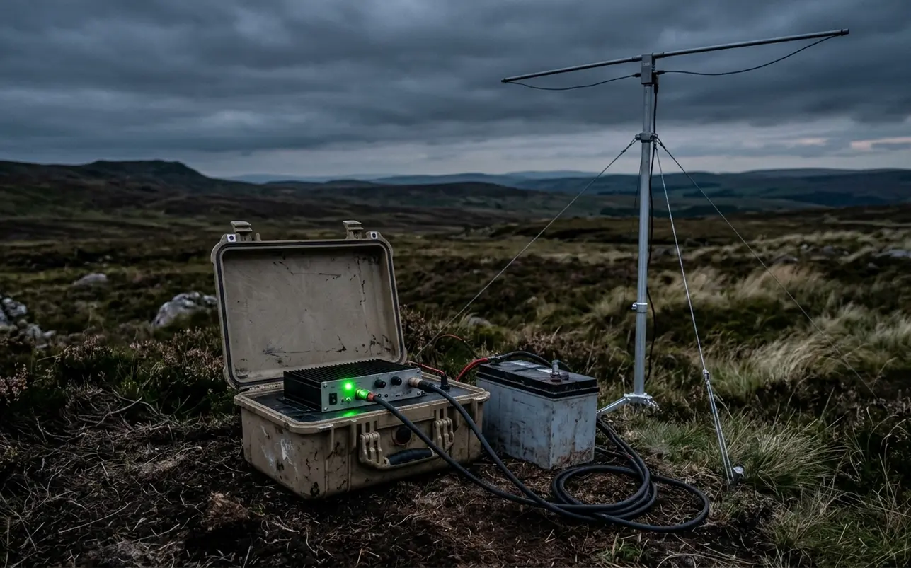
An off-grid transmission power system is a self-contained, direct-current (DC) energy-storage and regulation network engineered to sustain continuous remote radio transmissions without introducing mechanical sound or electromagnetic interference into the programme audio. In practice, the system boundary encompasses the battery bank, branch circuit protection, DC distribution bus, voltage regulation stages, the FM exciter or transmitter, a headless audio playback unit, and any standalone signal processing interfaces.
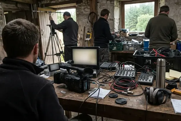
Consider the fundamental acoustic paradox of site-specific sound art & experimental installations. A production team hauls sensitive broadcast archives and transmission hardware miles into an untouched forest or valley, seeking an environment devoid of human machinery. Firing up a portable combustion generator immediately contaminates that isolated soundscape with a persistent low-frequency mechanical drone. When the composition reaches its quietest passage—the deliberate silence between electronic tones—an engine's exhaust note becomes an unintended, dominant part of the work.
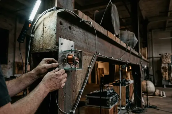
Eliminating the generator removes local combustion exhaust and mechanical rumble at the installation site, making solid-state battery architecture mandatory when broadcasting delicate electronic music across remote terrain. However, true acoustic silence requires looking beyond the power source to the thermal design of the transmitter itself. A battery-fed rig remains acoustically compromised if the FM exciter relies on an internal, thermostatically controlled cooling fan. Minutes into a transmission, as the internal heatsink warms, the fan spins up and breaks the stillness of the clearing. Field engineers must explicitly specify passive cooling across every enclosure, using conductive mounting plates and external heatsinks to shed thermal energy silently into the night air.
Amperage Draw Calculations Across a 24-Hour Cycle
Sizing an energy bank for a 24-hour sonic intervention begins with empirical measurement rather than datasheet estimates. Every device in the broadcast chain must be metered at its DC input while performing its exact operational task. The headless player should read actively from its designated storage medium, the audio processor must run its live DSP chain, and the FM transmitter must operate into a properly rated dummy load prior to any authorized antenna test.
A frequent engineering error in field radio transmissions is equating a transmitter's radio-frequency (RF) output rating with its total DC power consumption. A 10 W RF output specification describes only the power delivered toward the antenna feedline. Inside the chassis, the RF power amplifier, frequency synthesis stages, control logic, and internal voltage regulators consume substantial electricity, with the majority of the difference leaving the circuit as heat. Separate the silent-broadcast energy ledger into three distinct columns: watts leaving the antenna, watts warming the sealed transmitter case, and watt-hours keeping the unheard composition running until dawn.
Converting Watt-Hours to Bank Capacity
Electrical sizing relies on standard DC power relationships: power equals voltage multiplied by current (P = V × I), and amp-hours equal current multiplied by time (Ah = I × hours). When a rig incorporates mixed supply voltages—such as a 12 V transmitter alongside a 5 V headless player—adding device-side amp-hours across different voltage rails yields a distorted budget. Always calculate and sum watt-hours first, then divide the total battery-side energy requirement by the nominal voltage of the primary battery bank.
Take an illustrative energy budget to model the math (using hypothetical planning values rather than measurements from a specific hardware model):
- FM Transmitter: 30 W continuous DC draw
- Headless Audio Player: 5 W continuous DC draw
- Signal Processor / Interface: 3 W continuous DC draw
These three loads total 38 W at the device inputs. Across a continuous 24-hour broadcast window, the system requires 912 Wh of energy (38 W × 24 hours). Divided by a nominal 12 V supply, 38 W translates to an average current draw of approximately 3.17 A, accumulating to 76 Ah over 24 hours. This baseline figure exists before factoring in voltage regulator conversion losses, startup current peaks, and the battery bank's mandatory unused reserve.
Field Metering Protocol
Insert a battery-side watt-hour meter inline during a full 24-hour studio rehearsal into a dummy load. This single reading captures regulator overhead and tracks rising input current as battery voltage gradually falls.
Deep-Cycle Leisure Chemistry and Parallel Wiring
Selecting the chemical foundation for a remote power bank requires weighing delivered watt-hours at expected overnight temperatures against the physical mass that must be carried to the transmission site. Both Absorbent Glass Mat (AGM) lead-acid and Lithium Iron Phosphate (LiFePO4) chemistries serve in field production, each presenting distinct operational trade-offs as detailed in National Renewable Energy Laboratory battery storage guidelines.
AGM batteries offer straightforward charging topologies and robust cold-cranking resilience, though subjecting them to repeated deep discharges severely shortens their service life. LiFePO4 cells provide a much flatter voltage discharge curve and yield substantially more usable energy per carried kilogram—a critical metric for hike-in special projects. However, lithium systems introduce complex battery-management electronics and strict thermal limits; many LiFePO4 units prohibit charging below freezing unless equipped with internal heaters or low-temperature cutoffs, a vital consideration if solar replenishment is planned at daybreak.
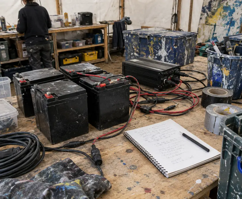
When a single battery cannot supply the required watt-hours, wiring multiple 12 V batteries in parallel multiplies capacity while preserving the native 12 V architecture. Connecting two nominal 12 V, 100 Ah batteries in parallel creates a nominal 12 V, 200 Ah bank (whereas a series connection would double the system voltage to 24 V and damage 12 V broadcast gear).
Parallel Bus Assembly and Circuit Protection
- Equalize Branch Resistance: Cut positive and negative interconnects for each battery to the exact same length from identical gauge copper cable before terminating them at common distribution busbars. Unequal branch resistance forces one battery to supply or absorb more current than its partner during heavy load cycles.
- Size Conductors for Voltage Drop: Select cable gauge to satisfy both safe ampacity and minimal voltage drop. In a worked electrical example, a 1 m outward run plus a 1 m return of 6 mm² copper conductor carrying 20 A loses approximately 0.12 V at room temperature, excluding terminal contact resistance.
- Execute Mechanical Crimps: Terminate cables using properly sized copper lugs compressed with a matching hex die and ratcheting crimp tool. Perform a physical pull-check on every termination, insulate exposed metal barrels with adhesive-lined heat shrink, and mechanically support the harness so cable weight never loads the battery studs.
- Install Primary and Branch Fusing: Mount a primary fuse immediately adjacent to each battery's positive terminal, before the conductor reaches the common positive busbar, and fuse outgoing equipment branches separately. While an inline blade fuse can protect a low-amperage audio player branch, its DC interrupt rating must match the system; a high-capacity lithium bank with massive short-circuit current potential requires a high-interrupt-rated battery fuse rather than a standard automotive blade holder.
Voltage Regulation and RF Noise Suppression
A battery bank's terminal voltage declines steadily over a 24-hour discharge cycle. If the supply sags below the transmitter's minimum input threshold, the hardware may suffer reduced RF power output, audible distortion, loss of phase-locked loop (PLL) synthesizer lock, or an abrupt undervoltage shutdown. Engineers must map each device's allowable input voltage window against the battery bank's fully charged peak and its planned discharge cutoff, inserting voltage regulation where those boundaries conflict.
Regulator selection directly impacts both thermal management and audio purity. A buck converter steps voltage down, a boost converter raises it, and a buck-boost topology maintains a steady output as battery voltage crosses above and below the target rail. By contrast, a linear regulator requires constant input voltage headroom; once battery voltage drops into its dropout margin, it can no longer hold a stable 12 V rail. Linear regulation also sheds excess voltage entirely as heat according to P = (Vin − Vout) × I. Dropping a freshly charged 14 V supply down to 12 V at a modest 2 A draw generates 4 W of continuous waste heat inside the weatherproof enclosure.
While switching DC-DC converters avoid this severe thermal penalty, poorly filtered pulse-width modulation (PWM) circuits, unshielded inductors, or unstable light-load operating modes can inject conducted and radiated high-frequency interference directly into the programme audio. Audible whine often occurs when switching harmonics are demodulated by sensitive analog stages downstream. Therefore, any regulated rail must be tested under full RF load during rehearsal to confirm it remains silent across the entire battery discharge curve.
Preventing electromagnetic feedback requires strict physical layout and grounding discipline:
- Star Distribution Topology: Build the DC return network around a single common distribution point. Route each load's positive supply and negative return together as a tight pair, keeping high-current transmitter supply leads physically separated from low-level analog audio interconnects.
- Local Filter Placement: Mount input and output capacitor filter networks directly at the regulator terminals rather than at the far ends of long internal wiring runs.
- Common-Mode Choking: To suppress stray RF currents riding on power leads, pass both the positive and negative conductors of a DC pair together through a ferrite core positioned immediately inside the enclosure entry. Select a ferrite mix specifically rated for the offending interference frequency band, as an arbitrary clip-on core offers little attenuation outside its target spectrum.
- Signal Isolation: Never defeat or lift required protective earth connections in an attempt to silence an audio hum; eliminate unintended ground-return loops using galvanic audio isolation transformers or properly wired balanced interconnections.
Enclosure Weatherproofing and Cold-Weather Capacity
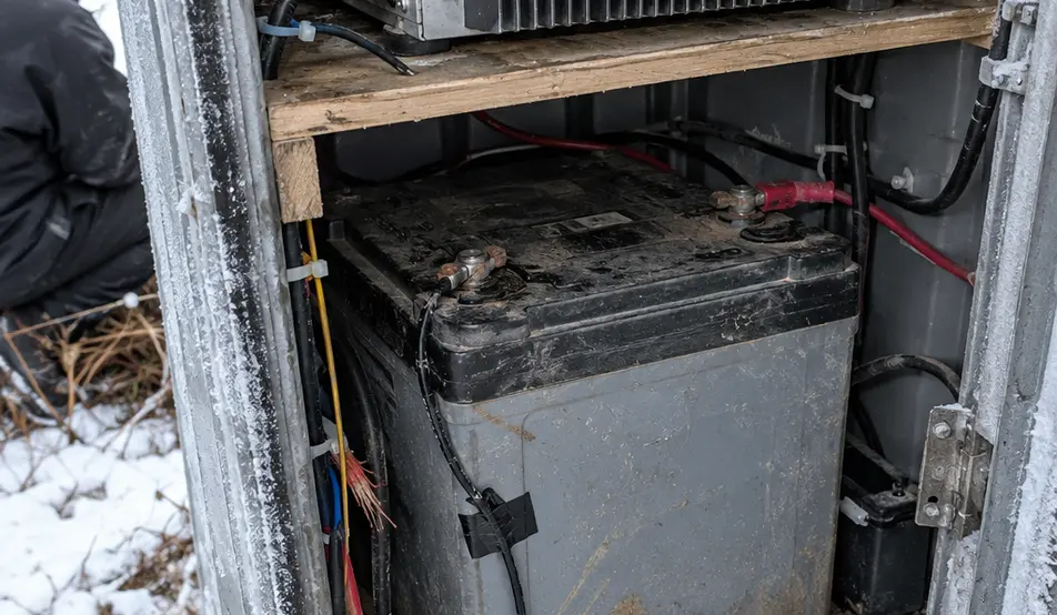
Deploying electronic instrumentation into exposed country requires treating moisture exclusion and heat rejection as a single mechanical problem. A hermetically sealed plastic transport case traps humid air alongside transmitter waste heat. To prevent internal condensation and thermal throttling, isolate the battery bank in its own compartment separate from the RF electronics. Valve-regulated lead-acid batteries—including AGM units—can vent gas during charging or fault conditions, requiring manufacturer-specified ventilation rather than an airtight enclosure shared with potential ignition sources.
Elevate all enclosures off saturated ground, route external coax and DC cabling through downward-facing drip loops before they enter weatherproof glands, and shade the rig from direct solar radiation without wrapping the external transmitter heatsink in thermal insulation. A pressure-equalizing membrane vent prevents vacuum lock as temperatures fluctuate, while a gasketed conductive mounting plate transfers amplifier heat cleanly through the case wall.
When wiring battery management systems or charge controllers that rely on thermal compensation, adhere to one strict placement rule.
Thermal Sensor Isolation
Affix the battery-temperature probe directly against the side of the battery casing, never inside the transmitter bay. Heat radiating from the RF amplifier heatsink will otherwise mask how cold the chemical bank has become overnight.
Overnight temperature plunges in remote valleys degrade battery electrochemistry long before the morning teardown. Cold temperatures slow the internal chemical reactions within lead-acid cells, increasing internal resistance and reducing deliverable capacity before the system hits its low-voltage cutoff. Passive case insulation slows the rate of cooling, yet it generates no heat of its own; a dedicated cold-weather margin must be added to the watt-hour budget during initial design.
When engineering a winter broadcast using manufacturer discharge curves that specify a one-third capacity drop at 0°C (32°F) for the chosen discharge rate and endpoint voltage, a 100 Ah lead-acid bank effectively behaves like a 67 Ah unit once the core temperature freezes. This establishes the freezing-bank boundary: a 24-hour FM installation can hit its low-voltage cutoff and go silent before dawn with substantial electrical charge still chemically locked inside the plates—and once the sun warms the case, part of that apparent lost capacity returns without a charger ever touching the terminals, proving the freezing night air acted as a phantom load that restricted access to the energy reserve rather than consuming it.